The Wabi Sabi Sign – Interactive Light and Sound
Part 1: Design and Build Process
By: Eric Lorenz

When we obtained our studio’s entrance sign, we talked about treating it like an interactive installation. Our plan was to produce something that we could show off to clients and colleges when they came in and spark creativity or leave them in awe. Having done a few interactive installations, I immediately started brainstorming with the team as to what we all wanted. In Part 1, I will talk about the process for brainstorming, designing, and building the hardware for this installation.
For this particular task, I wanted all members of Wabi to customize and make the installation their own. This is a chance to influence every member of the company to create their own installation and I want to try and encourage everyone from Audio Directors to Interns to give it a try. So instead of putting something together calling it done, I needed to create a framework for all to dig into and customize if they wanted. The two simple requirements for this sign were 1) make sounds and 2) back-light the sign. So let’s go into detail on my process for creating such an installation….
The Arduino – The Sights
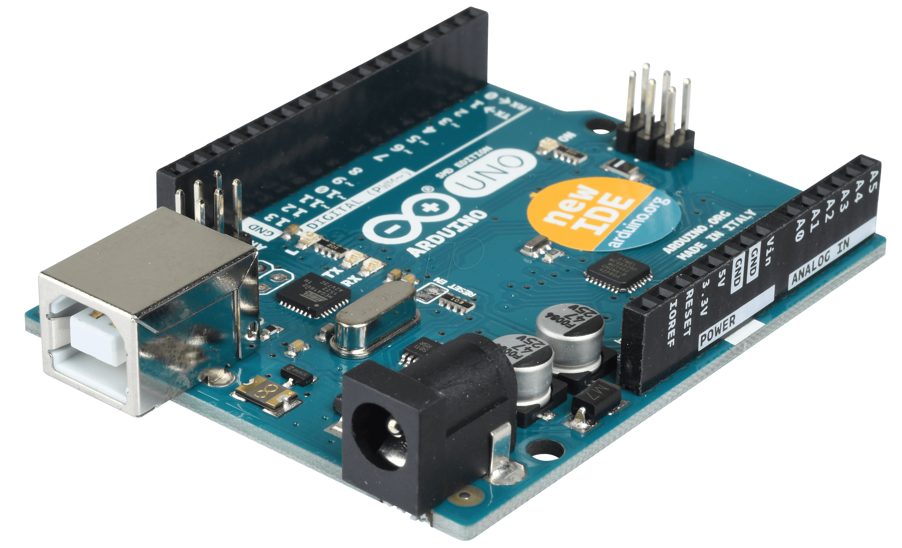 The Arduino is a powerful little microcontroller! I have had the privilege of working with this product many times and it’s an absolute joy. I set out to utilize the Arduino to control a 60 piece strand of NeoPixel LEDs, and control the lights with knobs or joysticks. When finished, you would be able to use these components to control brightness, sequences, program, and positioning of the LEDs.
I’ve done a couple of tests and experiments using the NeoPixel LEDs, playing with switching between light programs and tinkering with their parameters. While exploring different types of programs and sequences I could edit and adjust, I landed on some some very fun results. Here is an early prototype of those explorations.
The light show is comprised of 3 different programs and a modulator or two for each set. The Arduino and the Axoloti work in tandem to create an audio visual experience that is crafted for the performer to experiment and play with.
For each light program, I tried to represent it’s sonic texture in the color, speed, or intensity. The first program is a cycling light, and the first modulator changes it’s color based on a cutoff filter, the second changes brightness with a feedback delay. The second program is a set of 5 led lights that move around the strand based on the direction of the joysticks. Finally, the third program is a bright rainbow wave cycle, and the modulator manipulates the speed and spread of the wave for each color profile. You can stretch it out to make the whole strip a single color, or constrain it to make each LED a different color, and everything in between.
The final results of the light programs (with explanations)
The Axoloti – The Sounds
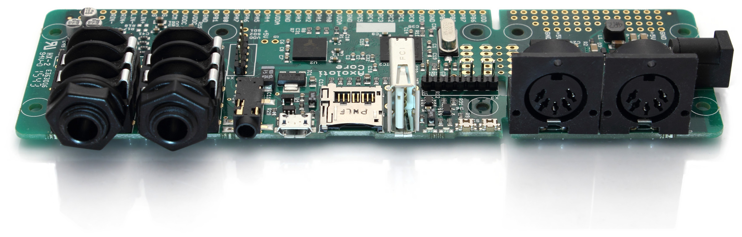
I’ve had my eye on this product for a while. It has the analog input control of the Arduino and and a similar node based programming language of Pure Data/MaxMSP. Furthermore, its suited to be used for audio synthesis and modulation, so any sound designer interested in creating their own custom synths, I highly recommend tinkering with one of these. It comes with a huge library of different oscillators, filters, data logic, and easy access to audio and MIDI controls.
I started to play around and prototyping synths with a breadboard and some electronic components. I wanted to test out what this microcontroller could do and to see what kind of synth I wanted to set out to create for the sign. Vocal modulation has always been a personal favorite when it comes to testing out DSP, so my early explorations into the Axoloti sounded a little like this…
One night, I had an idea to create a self-evolving, chaotic, synth that if left alone would feel like it had a mind of its own. I experimented with connecting multiple LFOs so each LFO influenced the other. Axoloti’s GUI includes an oscilloscope that lets you see the waveform, which helps understand how these connections work. This combination results in a waveform that shifts around from Min -> Max in unpredictable ways.
Going off of this idea, I then created two more independent synths that follow this LFO chaos mentality, and have another patch that utilizes the audio input function for microphone similar to my first test.
and here is a demonstration of all the synths
Putting it all together
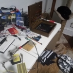
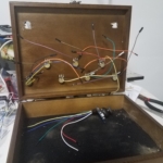
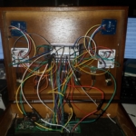
Because I wanted all the components of the box to allow full customization, I decided to make a patch bay that gave a person the ability to re-route and re-program everything without having to take out any wires. The controller is set up in such a way that allows you to patch all knobs and joysticks to a common +5 voltage bus, a common ground bus, and 11 analog out buses (one for each modulator component). In a sense, this is the easiest way to switch around what knob or joystick is controlling which part of the synth.
The Axoloti has 15 different analog inputs that I can use to connect and control synths with all sorts of hardware: joysticks, pressure sensor, buttons, light sensors, distance sensor, so many different controllers to keep your creativity afloat. Although it would have been special to create a box with 15 different intractable components, I went with 7 knobs and 2 joysticks to keep it simple for this 1st iteration.
The Arduino Uno that I am using only has 6 analog inputs that I could directly input from the controllers, so this limited which controls I could use to modulate the LEDs. In my opinion, 4 of those analog inputs HAD to to go to the joysticks (one for x axis and one for y axis on each), it wouldn’t be as fun without it. So then the other 2 go to two knobs (one that controls synth pitch and feedback on a delay).
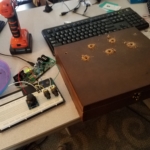
When it’s all working together, it really is a force to be reckoned with…
Still to come…
Part 2: Install and Launch!
My next task will be to cut up each individual LED and hang it up behind Wabi’s entrance sign…
~Eric Lorenz